Morven Farm Installation
This was a group project done in the penultimate year of architecture school. Our class visited nearby UVA organization ‘Morven Farm.’ We were tasked to pick a site and create an installation using timber and computer-assisted construction techniques.
The manufacturing techniques, like 3-D scanners and Rhinoceros’s Grasshopper were alien to us, so this project required a great deal of group cooperation. The site was also off-campus, and we were required to source our timber from Morven itself and other materials from stores around Charlottesville. Therefore this project also required an equal amount of group coordination.
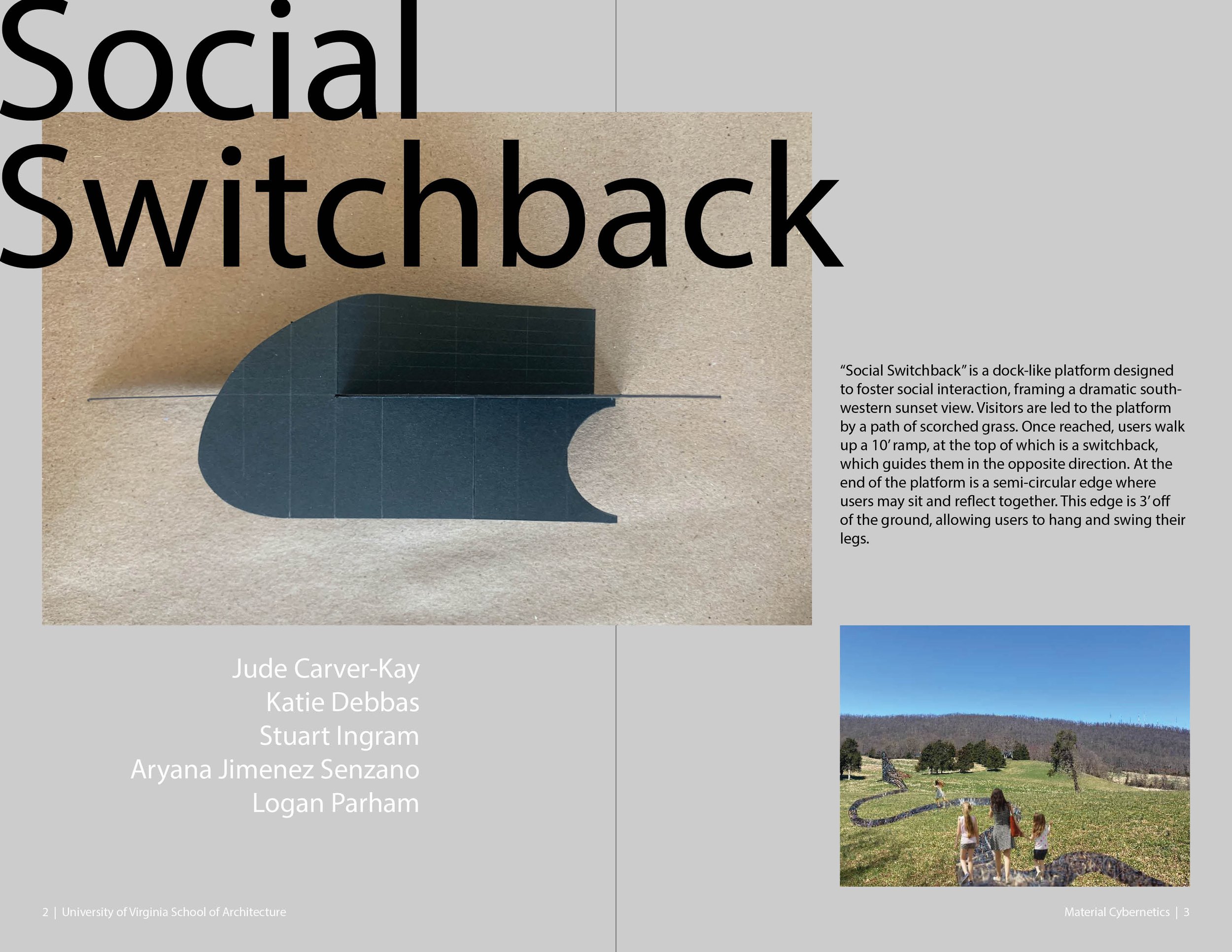
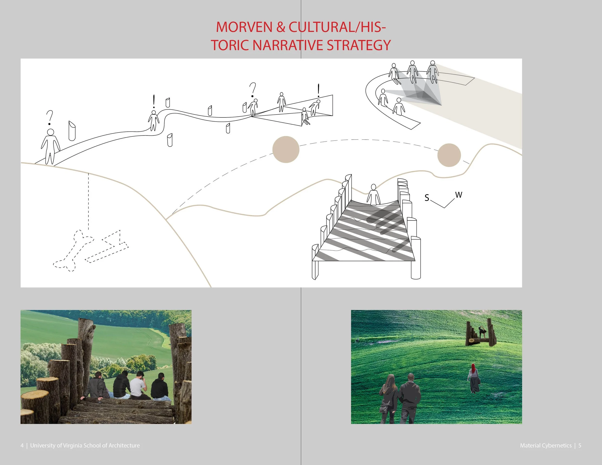
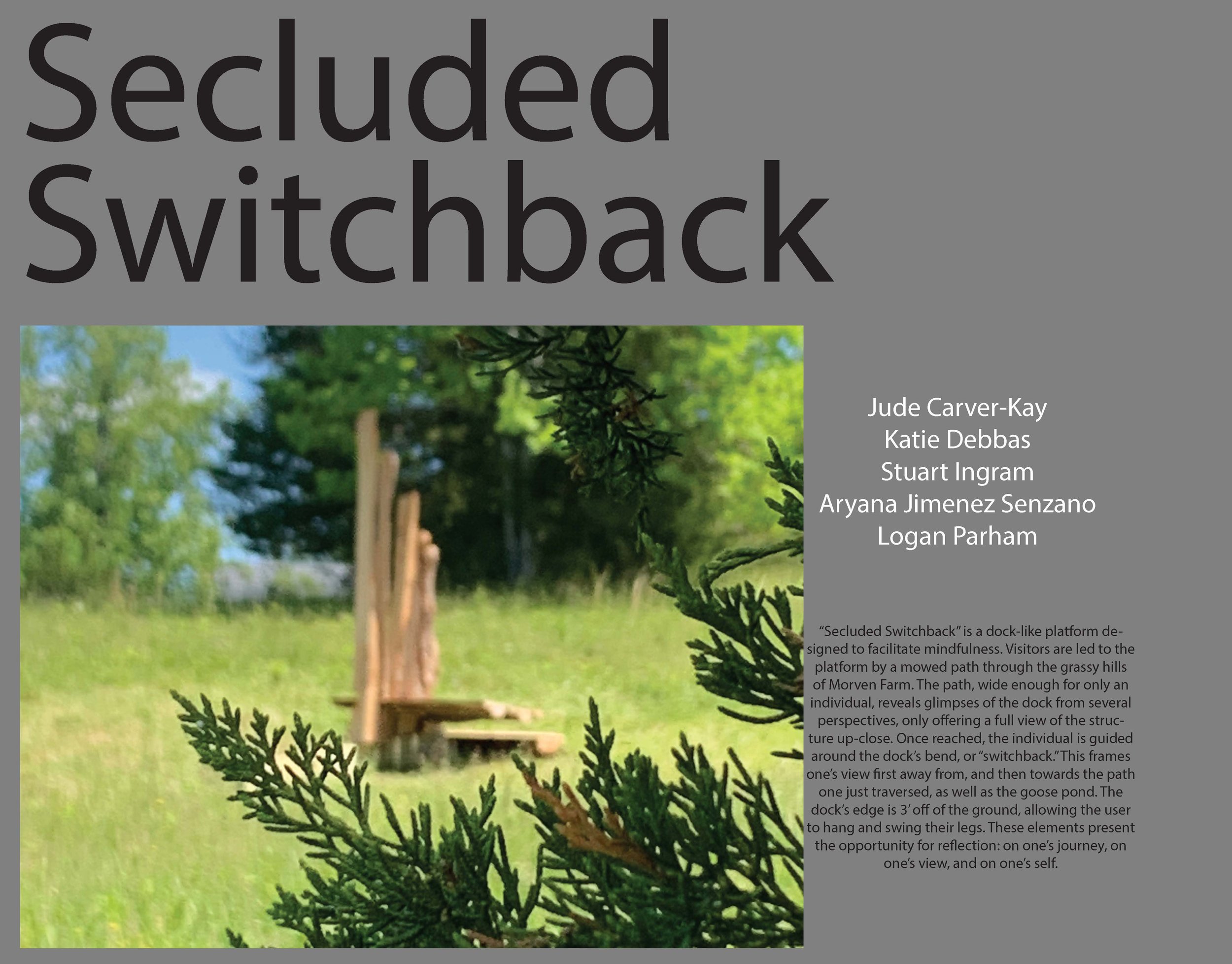
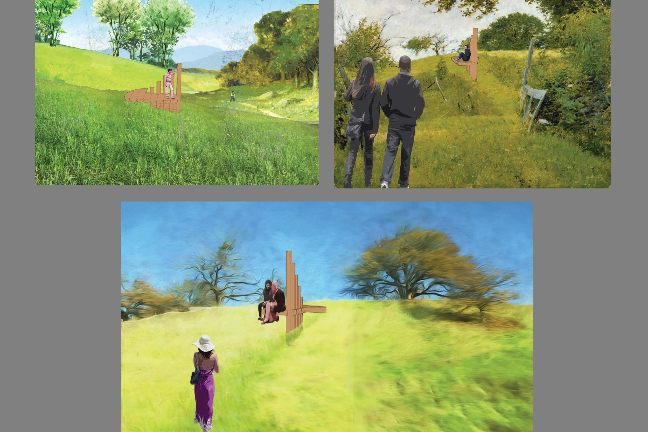
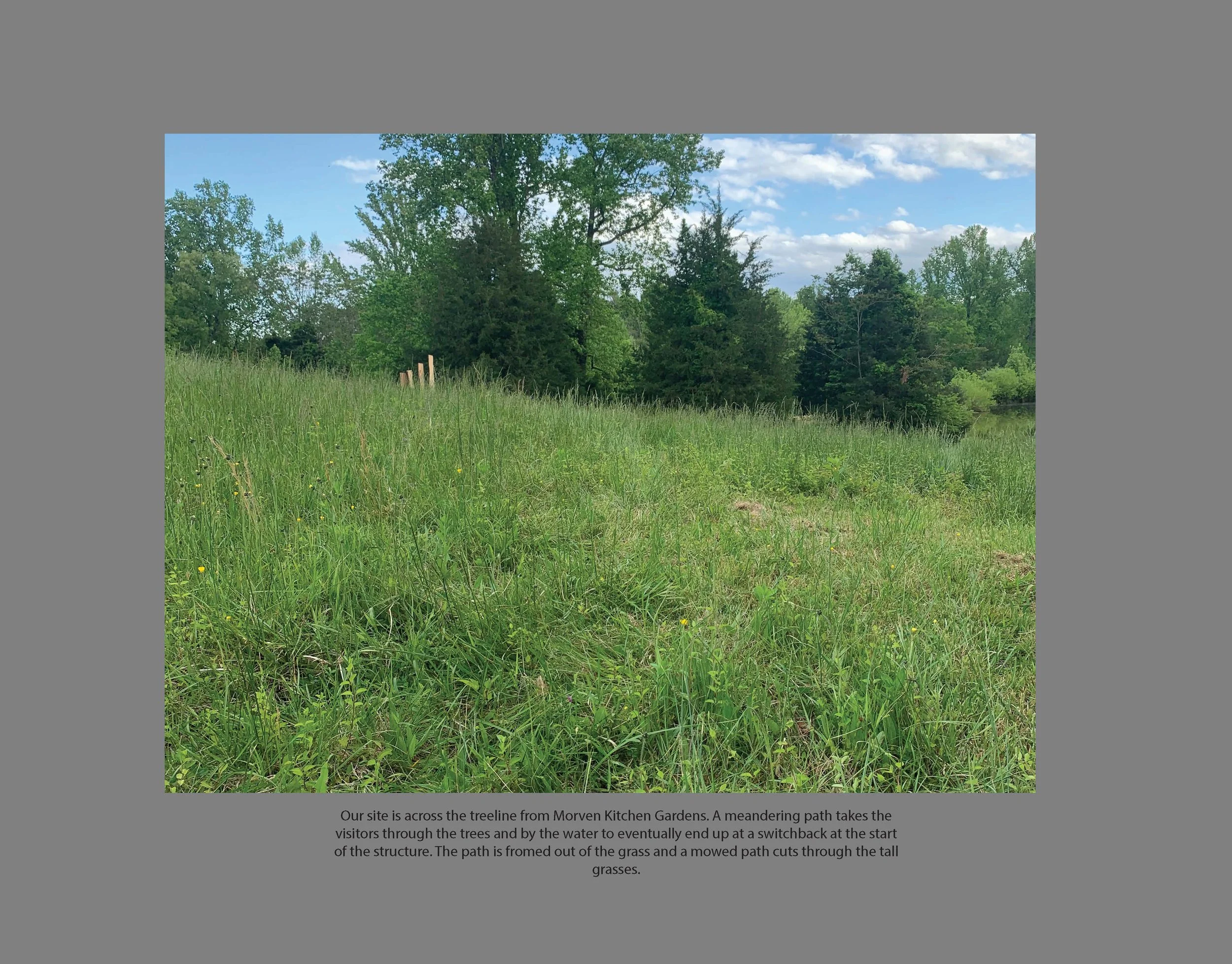
Here is the initial proposition of the project. Our group planned to make a small platform, made from timber offcuts. The joinery of the timbers would be solely friction fit, cut to shape by parametric software techniques (Rhino’s Grasshopper) and CNC milling. The horizontal axis would display the grain of the timber and the joinery technique. The vertical axis would filter sunlight through offcuts, thereby focusing the vista in front. A big part of this project is also the ‘approach’ of the platform. We wanted sitting to be the final step of a path, a meditation of the topography, nature, and history of the area.

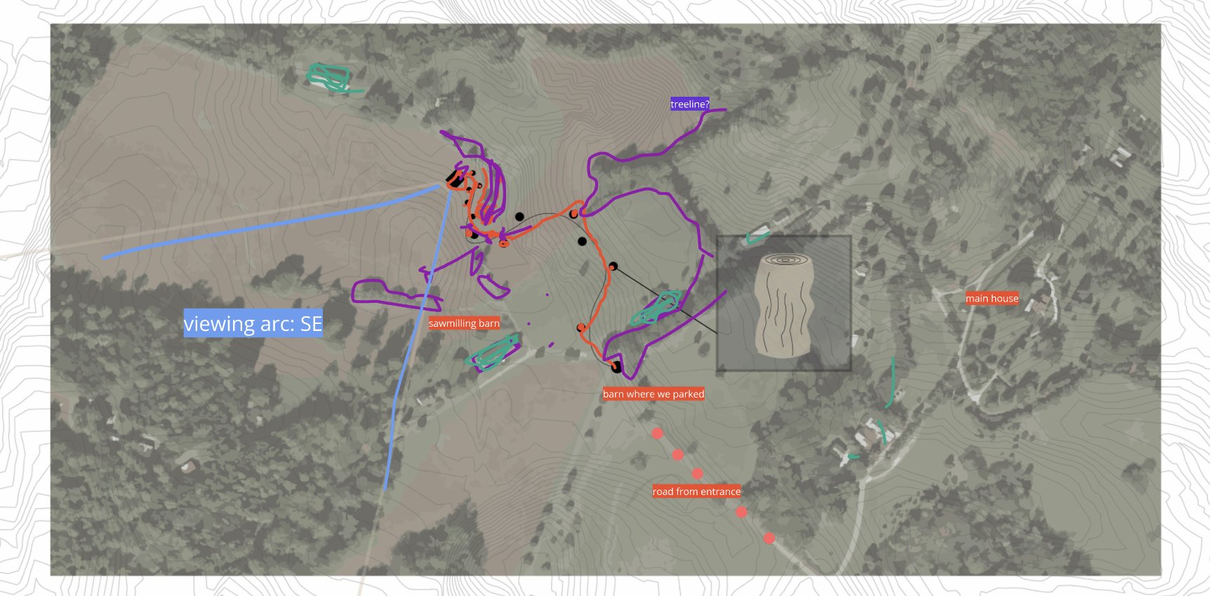
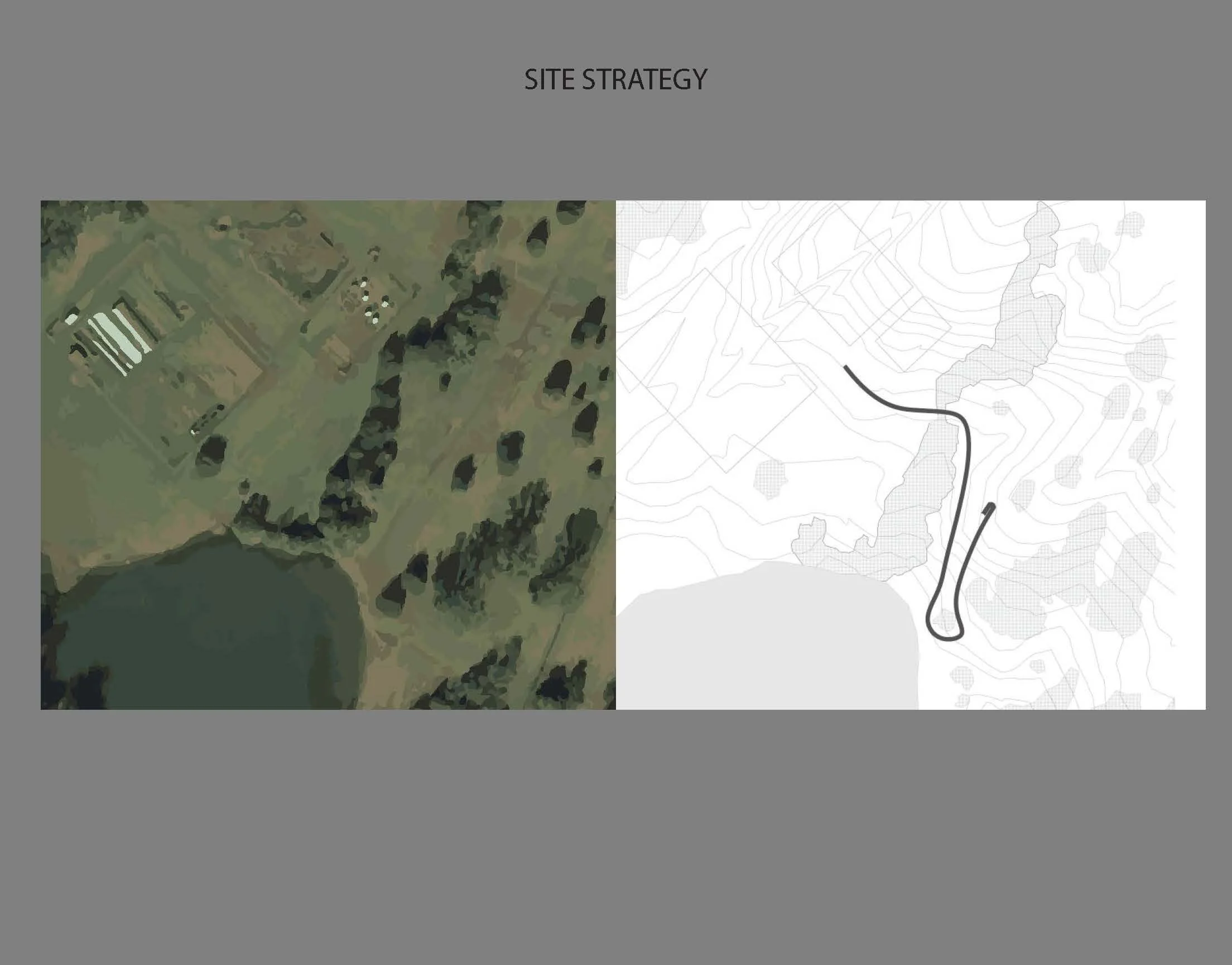
Top left is a preliminary design iteration. That architecture is then iterated into the one top right. We felt that the design on the right gave the visitor a path to follow - an orbit around the vertical stanchions and a destination at the sitting place. This aligns more closely with our narrative above and bottom right, the installation as a ending of an adventure through the farm. Bottom right is a topographical map of Morven, overlayed with scribbles on our workboard. We were discussing the site considerations - meandering, buildings, trees - on a video call.
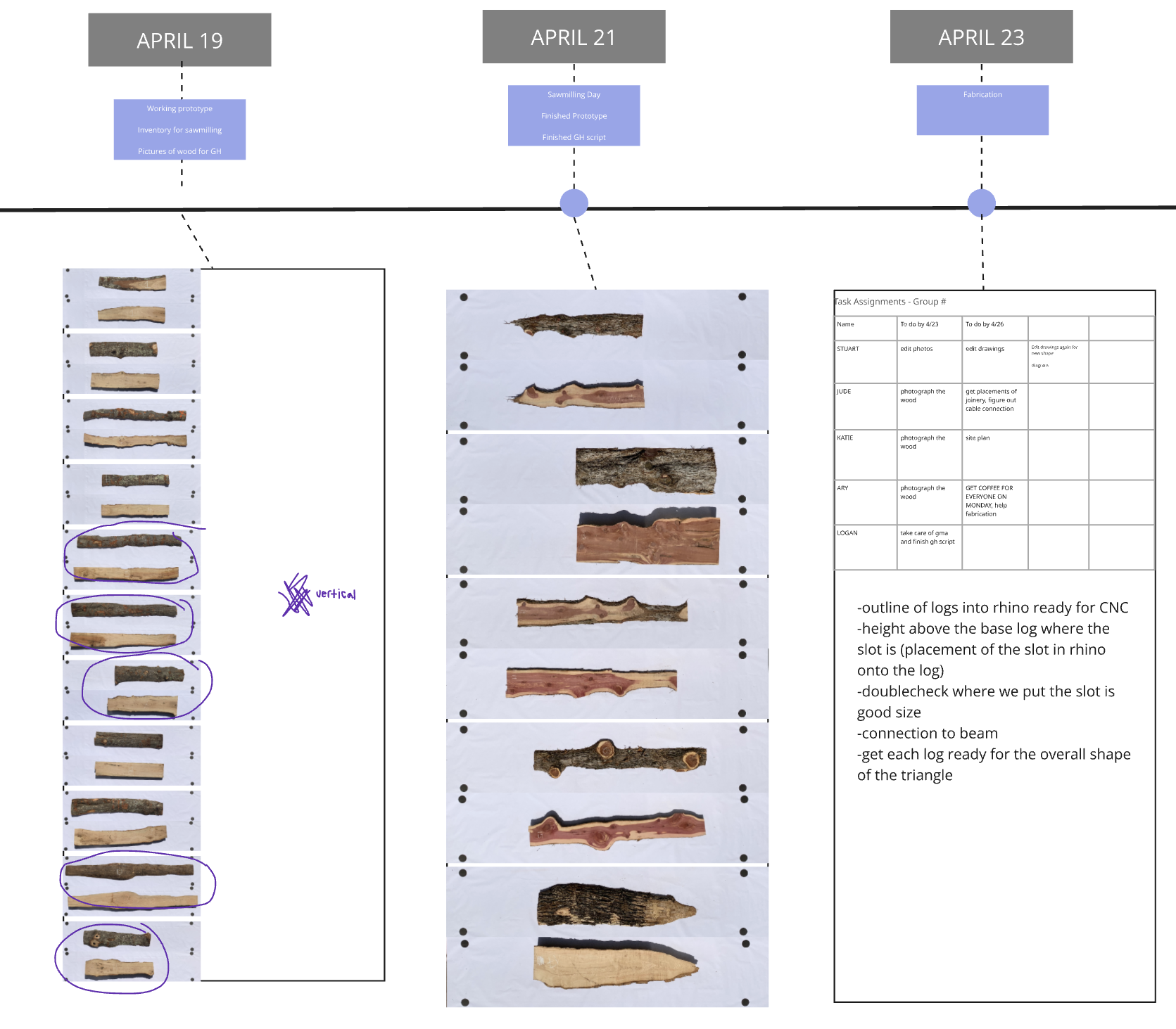
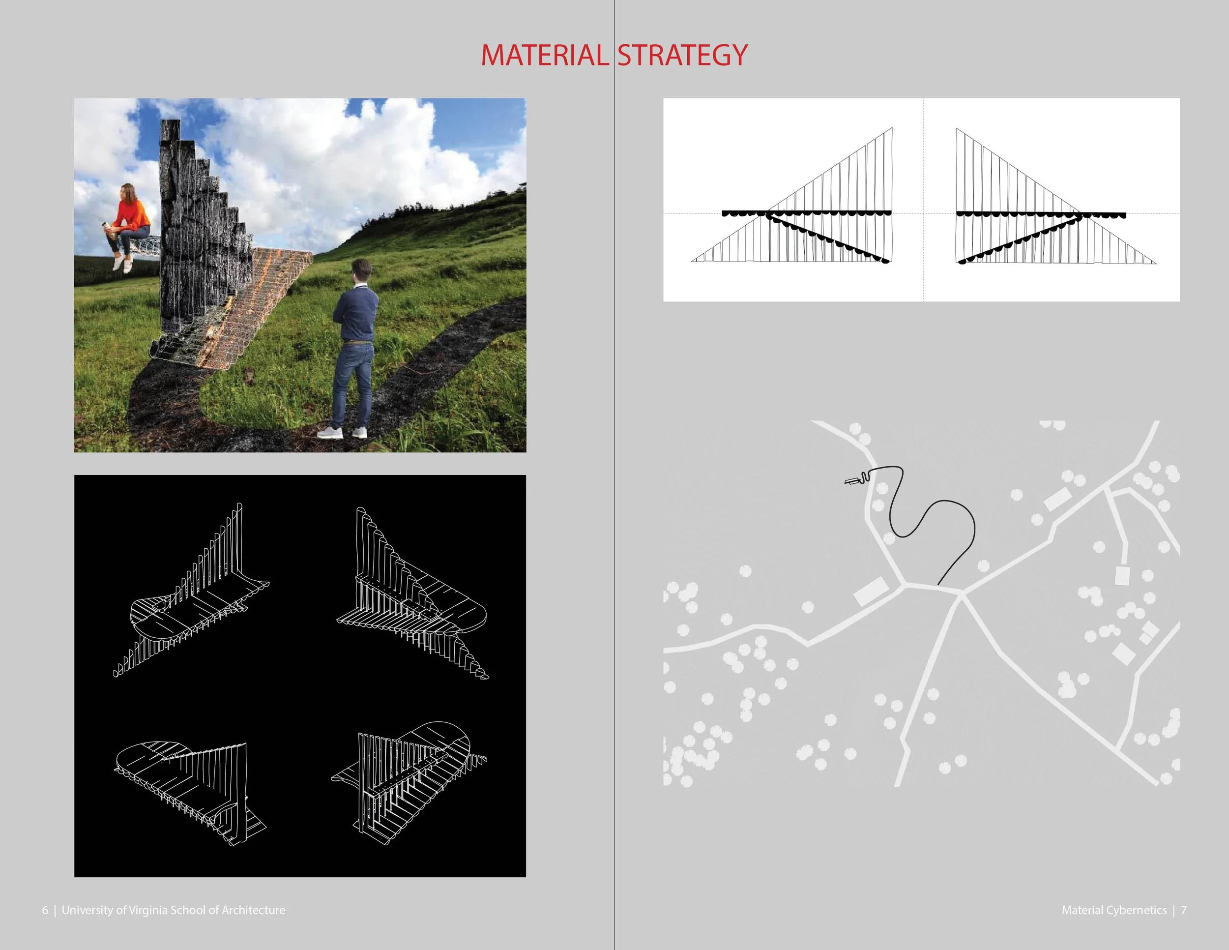
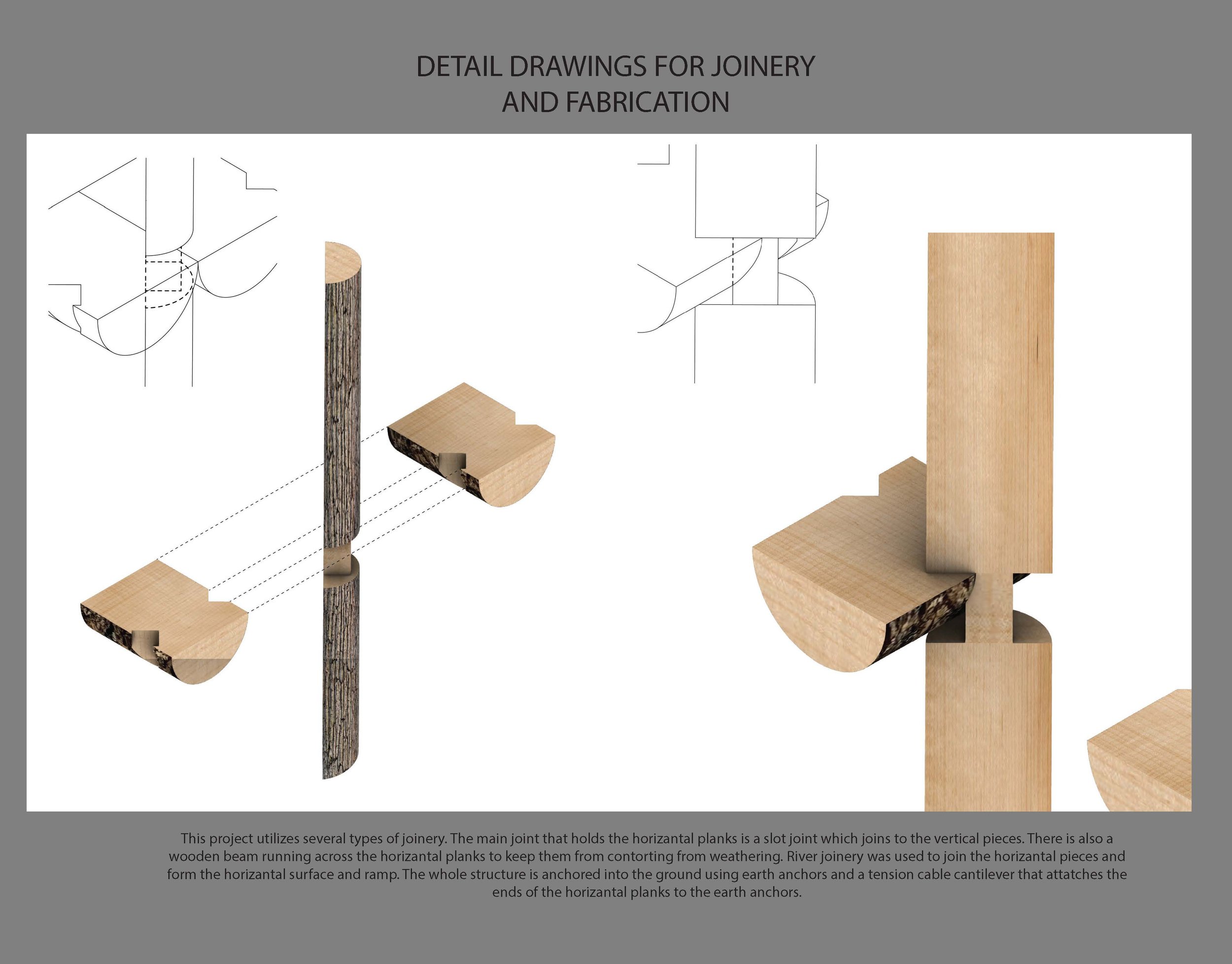
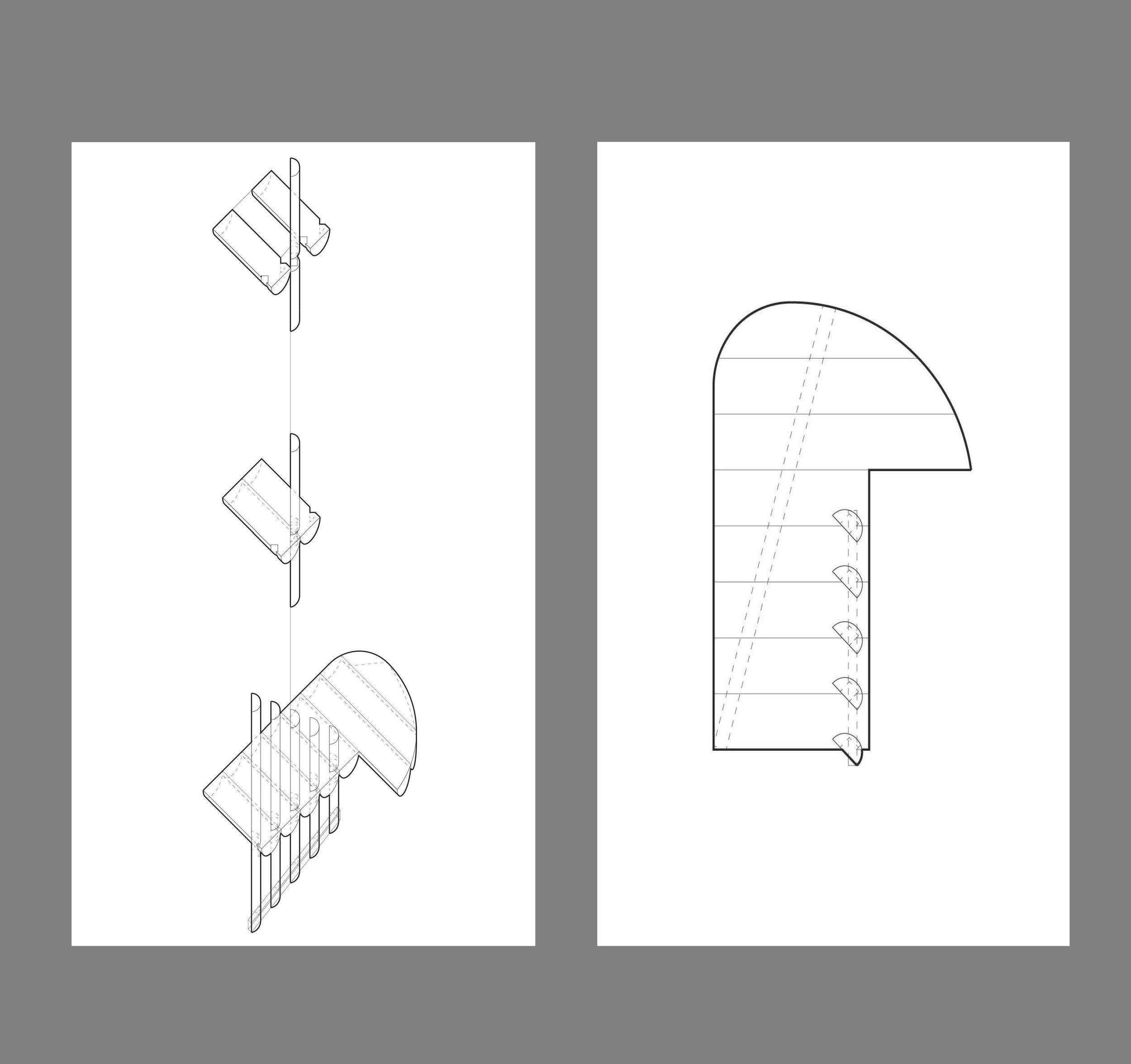
On the left are plan photos of the timber offcuts in our inventory (trees chopped at Morven farm). The plan outline is later used for the parametric edge joins. The live edge shape of one timber is milled into the adjacent timber. By the end of the milling process, the timbers have their own original live edge on one side, and a milled live edge on the other. This way each beam fits together perfectly, and each join is unique. The beams can also be organized in the platform.
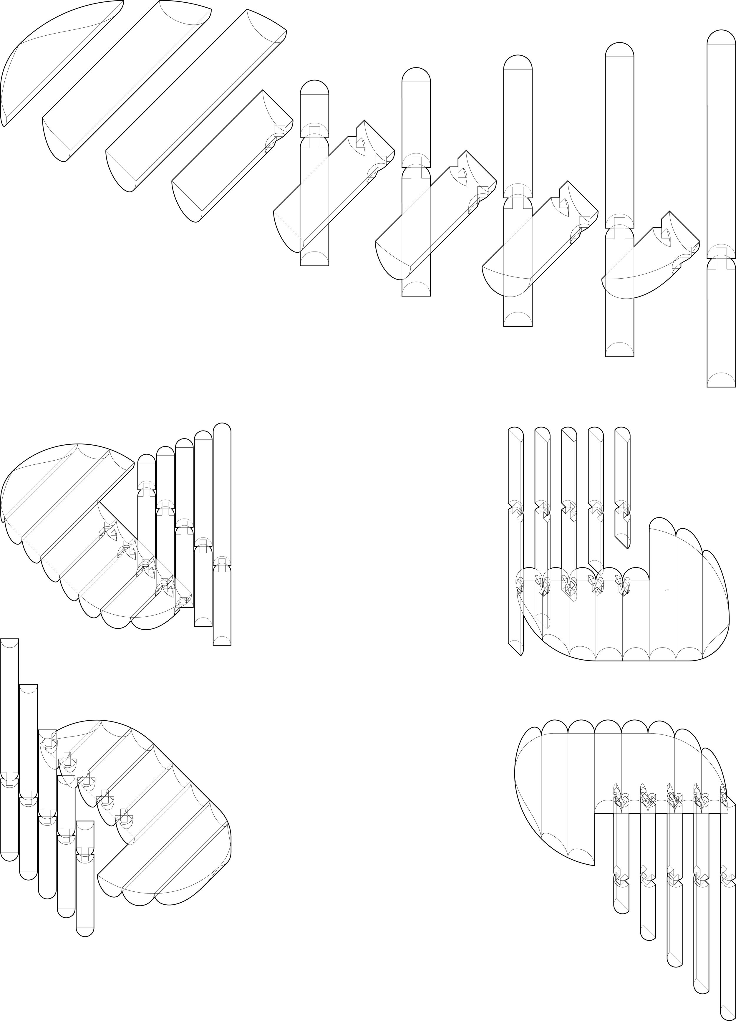
On the right are Rhino models of the joinery technique. The horizontal members would have unique notches milled out, and the vertical stanchions are milled down to a square cross-section. This way the horizontal and vertical members fit into one another, and the forces applied by the visitor increase the friction and resultant strength of the join.
The width of each beam timber not only impacts the aesthetics of the horizontal platform, but the spacing of the vertical stanchions, too, as each stanchion lies in between two beams - shown on the right. Using parametric design, the shape of the platform, the filtering of sunlight, the flexing of the wood under load, can all be modeled.


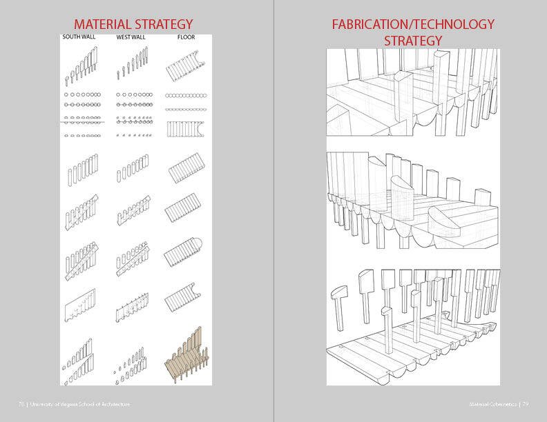
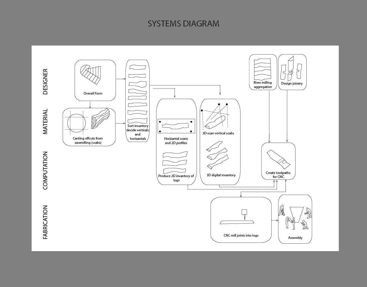
These are system diagrams for our own use throughout the project. We realized that we had to 3D scan the vertical members but the horizontal ones only required a planform scan. This is because the geometry of each vertical stanchion would have to be milled into the horizontal beams at the joint; below the square cross-section in the stanchion the live shape of the stanchion resumes and this live shape has to be milled out of the beam beneath the 90-degree notch. By doing this, not only are the square notches interlocked, but the live edges of the stanchions beneath the square is locked into the underside of the beam. This combination is what gives the joints such strength.
On the right is a diagram for assembly, which shows the cantilever system. We used earth screws and steel wire to pull the short end of the beams down, this downward force helps to counteract the weight of the visitor on the other side of the stanchions, on the long end of the beams.
This is the final review presentation.